|
-
 DC5 front lower control arm bushing install DC5 front lower control arm bushing install
DC5 FRONT LOWER CONTROL ARM BUSHING INSTALL
AIM: This is a guide to installing PCi spherical bearings into a steel DC5 LCA, but it will work equally well for Mugen hard rubber bushes or any of the other polyurethane options on the market. Not that I would recommend poly for the LCA but that is a story for another time. The process is the same for the JDM LCAs but be very careful of damaging them as the forces required to install and remove the bushes are significant.
Disclaimer: The following is provided as a GUIDE ONLY, and neither myself nor Ozhonda take any responsibility for the outcomes of someone else doing the following. You follow these steps at your own risk!
Things you will need:
Jack
Jack stands
A press (Mine is 20 ton and did the job well)
Various bits of pipe and metal to press the bushes in and out
A ball joint puller (I used the Honda OEM tool part number: 07MAC-SL00200)
An M12x1.25 nut
Pliers
Allen keys
19mm socket
17mm socket
14mm spanner
Breaker bar/ratchet
Torque wrench
Various 1/2" extensions
Drill
A 1+3/4" hole saw
Duct tape
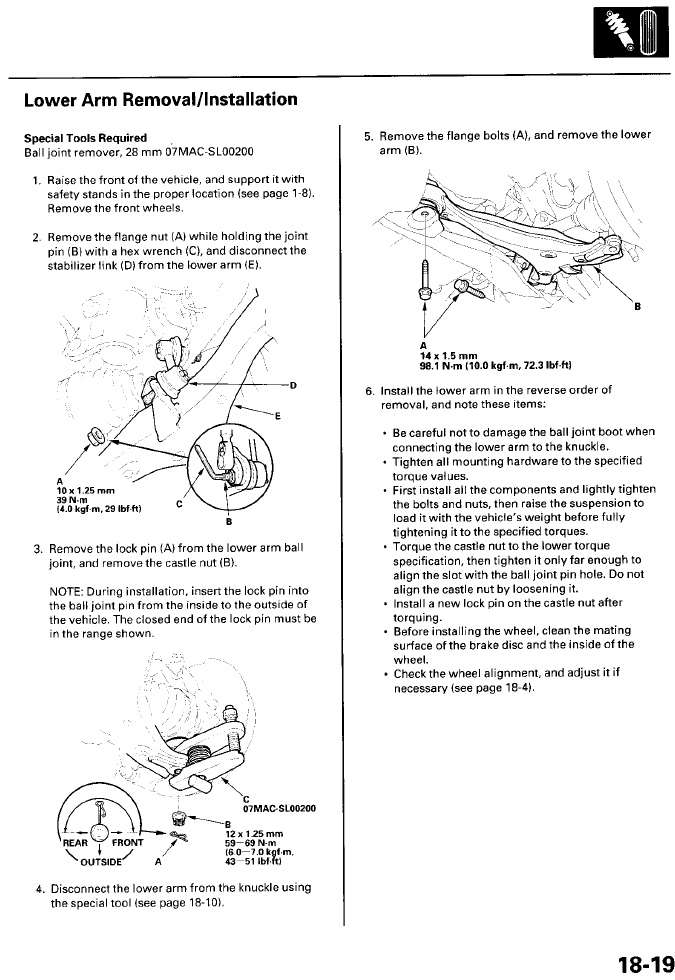
Figure 1: The relevant page from the workshop manual
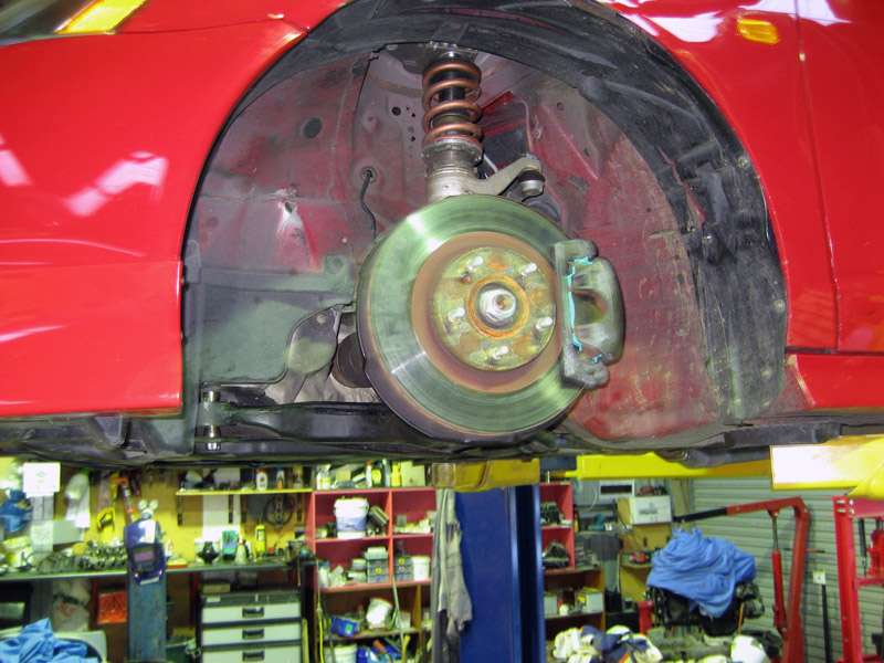
Step 1: Using a breaker bar and a 19mm socket (if you have OEM wheel nuts) loosen the front wheel nuts. Raise the front of the car up using the jack and place the two jack stands under the two front jack points. Remove both front wheels, and you should be faced with something like what is pictured in Figure 2.
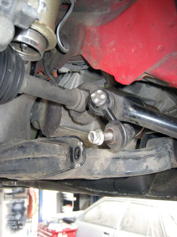
Step 2: Loosen but don't remove the two large bolts holding the lower control arm to the subframe, pictured toward the left of Figure 3, using a breaker bar and 19mm socket, refer to Figures 4 and 5. Loosen and remove the flange nut from the swaybar endlink with the 14mm spanner, using an allen key to prevent the link from spinning if necessary. Refer to Figure 6.
Figure 2: The car raised up
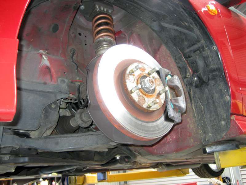
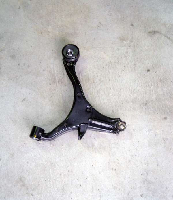
Figure 3: The lower control arm
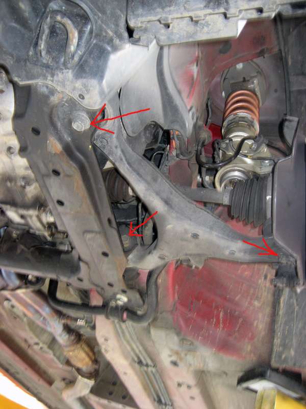
Figure 4: Removing the front LCA bolt
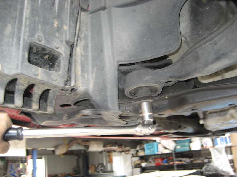
Figure 5: Removing the rear LCA bolt
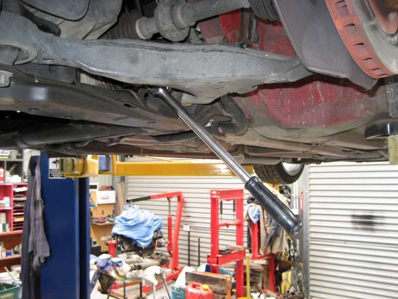
Figure 6: Removing the swaybar end link
Step 3: Using pliers remove the lock pin from the castle nut on the lower ball joint and loosen the castle nut using a breaker bar and 17mm socket, refer to Figure 7. Remove the castle nut from the ball joint stud and then put the M12x1.25 nut on in it's place threaded on until the bottom of the nut is level with the end of the stud. This is to protect the thread as you pop the ball joint out of the LCA.
Place your ball joint puller of choice on the ball joint as shown in Figure 8 and crank away on it with a 19mm spanner until the ball joint pops, taking care not to damage the threads. A few taps on the side of the LCA with a flat punch or drift and hammer sometimes helps the balljoint pop free.
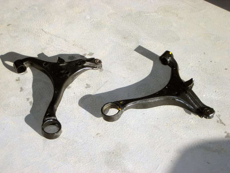
Step 4: Once you have popped the balljoint then completely remove the 2 bolts into the subframe and remove the LCA from the car. Repeat the above steps for the other side of the car which should leave you with 2 lower control arms as pictured in Figure 9.
Figure 7: Removing the ball joint castle nut
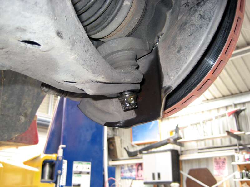
Figure 8: Popping the ball joint
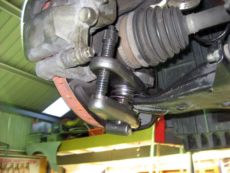
Figure 9: Lower control arms removed from car

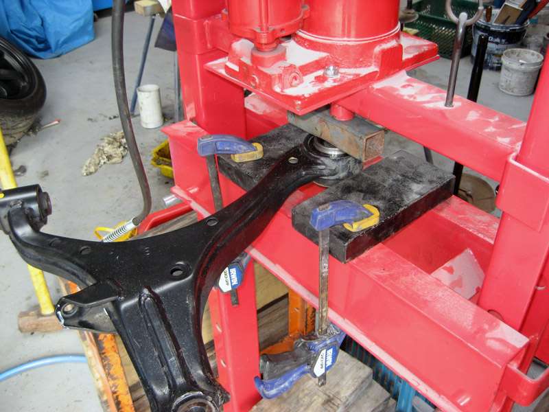
Step 5: Now comes the hard part, pressing the bushes in and out of the LCA. To press the large front compliance bushing out I used the inner race from a DC5 wheel bearing as shown in Figure 10. I pressed the bush out from top to bottom from memory but I am unsure whether it makes any difference. Repeat for the other LCA. The control arm with the bushes removed is shown in Figure 14.
Figure 10: Pressing out the compliance bushing
Step 6: Removing the rear bush from the LCA is a bit more involved. There is a steel flange on the bush that must be removed before the bush can be pressed out toward the front of the LCA, refer to Figure 11. The ideal tool to remove this is a 1+3/4" hole saw with duct tape wrapped around the pilot drill bit to match the inner diameter of the bush to keep the saw centred, as shown in Figure 12. Use some cutting oil and go slow and you should end up with something like what is pictured in Figure 13. Repeat for the other LCA.
You can then press the bushing out of the LCA. I used a 32mm socket and a 2" piece of pipe to assist me, no pictures though sorry. Once you have removed the two rear bushes then the LCAs should look something like Figure 14.
Figure 11: The rear bushing flange
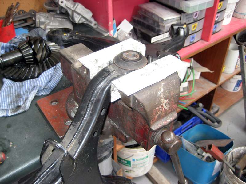
Figure 12: The tool
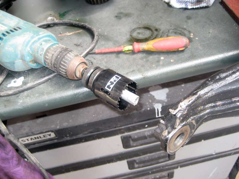
Figure 13: Flange removed
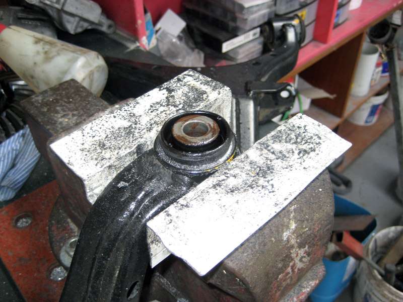
Figure 14: Bushes completely removed
Step 7: It is now time to install the PCi (or whatever) bushes in the LCAs. The bushes must be pressed into the LCA in a particular direction, each bush has a smaller end. If you look closely at each bush you will see a small step in the diameter of the smaller rear bushes and two small steps in the larger compliance bushing, the end of the bushing with the step must go into the LCA first. Be sure to press the front compliance bushing in with the arrow pointing toward the rear bushing, a few lines with a pen will help here.
I pressed the bushes in in the reverse direction to how I removed the OEM bushes, the compliance bushing from the bottom and the rear bushing from front. I used the same bearing race, length of 2" pipe and 32mm socket as I when I removed them. Take care to press them in perpendicular to the hole in the LCA. The LCA with the PCi sphericals installed is shown in Figure 15. The compliance bushing may be pressed in until the top and bottom is roughly flush with the top and bottom of the lower control arm.
Note that the grey housing of the rear bushing must protrude from the LCA by around 1.5mm toward the back of the car for the arm to fit correctly back into the subframe.
Figure 15: PCi sphericals installed
Step 8: All that remains is to install the LCA in reverse order of removal. Install the four spacers onto the LCAs and place the arm back into its place in the subframe and re-install the two large bolts and torque to 98Nm. Refer to Figure 16.
Clean the taper on the ball joint and re-insert the ball joint into the LCA. Put the castle nut on and tighten to 58Nm and re-install the lock pin ensuring that the pin points in the direction shown in Figure 1.
Re-install the sway bar endlink into the lower control arm and torque the flange nut to 39Nm. Repeat for the other side and you are all done. Refer to Figure 17.
Figure 16: Inner bolts installed
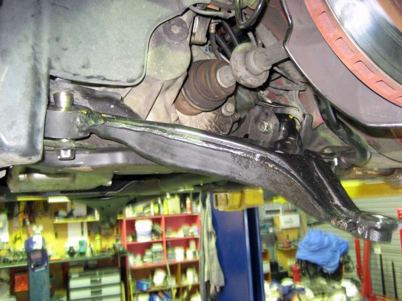
Figure 17: All done
Step 9: Put the wheels back on, lightly tighten the wheel nuts. Lower the car off the jack stands and torque the wheel nuts to around 110Nm. Get a wheel alignment as soon as possible and revel in the more precise handling afforded by the reduced compliance in your lower control arms and the added caster.
Feel free to make comment or ask any questions if any part of the DIY is not clear 
Tags for this Thread
 Posting Permissions
- You may not post new threads
- You may not post replies
- You may not post attachments
- You may not edit your posts
-
Forum Rules
|


 Reply With Quote
Bookmarks