|
-
Finally - Trunk Control unit installed: See Post 11 for a picture of the tablet and the system running on the test bench.
Wires lying around are for Amplifier speakers, power, remote on/off (mute) and 1 of the 5 audio leads - 4 short leads from the bottom of the control board (4Ch DSP out) are not connected as yet.
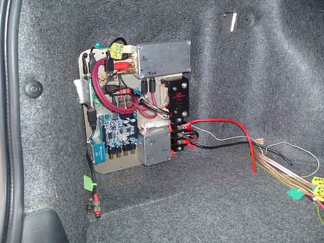
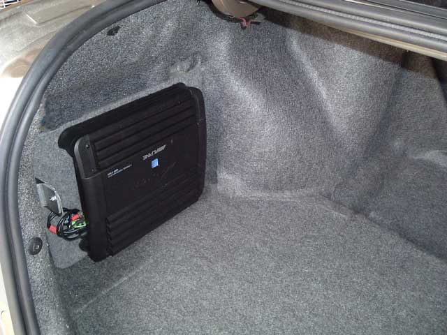
Below - the amplifier connected and locked in place over the control unit.
The trunk install is finished but for a cover plate over the Audio cables.
-
I just powered the system up for the for the time in the vehicle - always an anxious moment - waiting for smoke, or worse 
A few weeks ago I managed to get an old Radio board, the only purpose was to get the Head unit interface Socket off the board so I could use it to just plug this new install into the existing Head unit cable with No other connections to the Vehicle. This gives me lights on/off, Dash lights PWM (brightness), Accessory 12v, Steering Wheel control line and ground. I have also linked the front left/right speaker pins in the socket to the rear left/right socket pins lines. This means the rear speaker connectors are now front left and right speaker lines. The Amplifier is in the trunk and of course drives the rear speakers directly and now the front speakers via the bridged lines. No extra cables.
This is such a neat simple install as far as interfering with the vehicle existing wiring, now there are no taps or changes to anything in the vehicle wiring looms.
It powered up perfectly: 
I was eager to hear the sound (noise really) as I'm running audio out from the Tablet back to the Trunk mounted audio mixer, audio switcher, DSP and Amplifier - I was forced to do this because of troubles with USB Audio DACS I had tried, anyway with special heavy duty doubled shielded cables (only audio cables I'll use in a vehicle) its PERFECT, absolutely no noise, as clean as.
Big plus - DAB - FM sensitivity has improved 100% - far more that I had hoped for - No Video cables, noisy Mainboards and their dirty switch mode supplies and circuits to interfere with signals.
Now comes the Hard part - Mounting of the Tablet should be relatively easy but the Dash insert - That is going to take some time and effort but because of the results - I'm really looking forward to getting it completed.
As soon as I get the backing plate in I'll post a video of the system running.
-
Did a test drive yesterday - everything worked, however it will take a few trial and error fitments to get the best angle for viewing the reflective screen of these Tablets.
Warning Technical info on testing of the charger and thoughts on charging current and voltage.
There are 3 wired connected between the AC charger and the SP2 charging connection.
The centre pin is a sense connection (very thin wire) anyone trying to make sense of this without a CRO (oscilloscope) will be confused.
This line is a control line for the AC charger from the SP2 and is a 5v pulse that is present whenever the battery is charging. Without this connection the AC charger limits the available current and chops between 0 and 12 volts.
As you may know the SP2 battery can get quite hot when charging and testing the AC adaptor on a 78% charge reveals a DC input of 11.65 volts @ 3.3A.
Do you want this kind of charging current in a vehicle situation? I don't, as I believe it could shorten the life of the battery?
Testing with a current limited (3A) DC bench supply on an SP2 with 78% battery indicates:
SP switches to Charging @ 8.6V
Switches back to Battery @ 5V
Current @ 8.4V = 3mA
Current @ 8.6V = 800mA
Current @ 9V = 1.8A
Current @ 10v > 3A
As the SP2 Battery charges and current drops below 1.7A (fixed supply of 9V) the internal charging circuit starts chopping the charge current? Increasing the voltage and increasing the charge current to 1.7A stops it chopping.
Seems like it wants a min of 1.7A charging current and this may be what normally happens when the battery is charged to 100% - once it gets close to 100% charging current drops and increasing the voltage does not increase current above the Tablet power requirements.
Interesting point: The SP2 will switch to external power and not charge - but still runs from the external source.
The SP2 @95% charge, drawing 800mA from the Ext DC supply and "not charging" was set to Hibernate: Current dropped from 800mA to 25ma. So holding charge current is 25mA and when powered up, the SP2 is running from the external charging supply.
In the process of testing:
SP2 @ 100% - dropped DC voltage until current is around 25mA.
Wait to see what % of charge is reached before current increases and at what level the battery sits.
Goal: To determine the best voltage to use for holding the battery at near 100% while the external DC supply fully powers the SP2 - looks to be around 8.6 to 9 volts.
Thought so far:
I can use a simple linear 5A 3 terminal Voltage regulator - $6.00 - (no need for another noisy switch mode supply) add a current limit of say 1.5A and we should be good to go.
At the moment it's reporting Battery 96% charged - AC plugged in @ 96% and NOT charging.
Results to follow.
Last edited by MikeCl; 06-12-2014 at 04:21 PM.
-
Hi Mike...don't know of many TO3 package 3 terminal regulators that can handle 5A. I think most are rated to 3A but this is not continuous...or is with good active cooling! Yes you should be good to 1.5A...but just!
Brendan
-
Hi Brendan, yes the backing plate and compartment for the tablet it a big sheet of thick aluminium so cooling for a T03 device is not a problem. I'll be adding current limiting to 2A in any case so even a 3A device will be fine. Most current it will see will be charging and from then on around 800mA. Allowing for an input from the Alternator of 14.8v max and dropping this via a protection diode to around 14.3v will see around 6V @ 1A. Worst case has been 1.8A. Alternator output usually varies around 13.2V to 13.8V after a few minutes depending on load 90% of the time, so 90% of the time looking at 5V @ <1A. Will not be a problem.
Edit: Found - LM338 1-32V @ 5A, TO-3, will be easy to add current limit and set the desired Output voltage - which after further testing is 9V.
Last edited by MikeCl; 06-12-2014 at 05:14 PM.
-
Yep, well done. PDIP across the regulator @3A will be 14.8V - 9V = 5.8V x 3A ~ 17.5Watts. So, well within the TO3 specs. Even better if you use a Schottky for reverse protection as this will drop VIN, 14.8V, by around .4V ~.6V or so.
This is looking real nice indeed! Well done.
Brendan
-
Thanks, slowly getting there, BTW max current will be limited to 1.8A so worst case is 11W and 90% of the time <9W.
-
1. Basically finished the backing plate and almost set on the position.
2. Made a vehicle Charger/PSU for the Tablet.
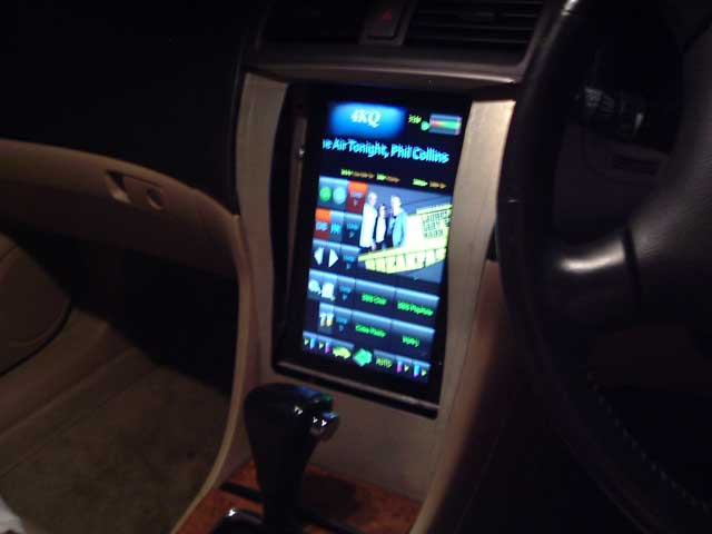
It's night time and I just fired the system up after installing the Charger/PSU, couldn't wait till morning, besides fire is easier to see at night So I snapped the 1st picture of the Tablet sitting on the Backing plate with everything connected and running. Again bad photo - no flash.
The Cover plate clips in and follows the curve of the dash. This is just the outer shell in aluminium, once I'm happy with it I'll be moulding curved and bevelled side pieces, again this is right at the start of making the cover plate/tablet surround so don't expect anything flash.
I was surprised just how much curvature is in the dash which is evident in the photo, this was never going to be a flush install in any case but from this rough picture I hope you get the idea.
FYI just a few of the (FE) Front End software features:
Auto Hibernates when vehicle is switched off. Auto mute/unmute on close, open and cranking.
The Mode button on the steering wheel switches (scrolls) through Phone, HVAC, GPS and Home screens and Radio or Music screen - whichever is active, each is announced so no need to take my eyes of the road.
Passenger and Driver temps are adjusted by the iDrive encoder (when the HVAC screen is showing) and temperature is announced - again no need to look.
Steering wheel Channel up and down buttons change song or DAB-FM station, the iDrive encoder and buttons between the seat control everything as well.
When GPS is showing, iDrive encoder zooms the Map in or out, changes view etc.
When Music player is on screen the iDrive encoder Scrolls the play list and pressing the encoder select a song.
If Phone rings and caller is in the phone book then Phone screen auto selects and call is answered with announcement of caller name, music/radio mutes/pauses and when call ends it unmutes and returns to the last screen.
If caller is unknown - auto switched to Phone screen, mutes as before and displays the Phone number (if available) one press of the iDrive encoder answers, another press hangs up.
Of course all of this can be controlled by the touch screen.
Last edited by MikeCl; 09-12-2014 at 08:06 AM.
-
2003 CL9 5AT *ECU REFLASHED*
CT-E Icebox|Ralco RZ pulleys|K&N filter|DC Header|250cell Cat|Cusco Tower & H Brace| H.Drive Coilovers | Rays RE30 18x8.5 | S/S Brakelines | Rigid Collars
-
always wished someone would mod a honda with a tablet.
please post up some youtube vids.
does this look like it also applies to the Accord Euro CL9?
-
We have the same interior so yes
2003 CL9 5AT *ECU REFLASHED*
CT-E Icebox|Ralco RZ pulleys|K&N filter|DC Header|250cell Cat|Cusco Tower & H Brace| H.Drive Coilovers | Rays RE30 18x8.5 | S/S Brakelines | Rigid Collars
-
Fredoops & kryptonite, thanks for nice feedback.
FYI here is the prototype car cradle and SP2 tablet power button on/off control using a solenoid.
I eventually came up with a way to control the tiny SP2 On/Off button. There are enough problems with the power button on a Tablet without the SP2 throwing a sloping side panel and button at you, it causes the SP2 to try and shift upwards away from the pressure being applied to the switch, add to this the fact that the switch have VERY LITTLE travel before it operates and it becomes a pain if there is any movement in the tablet, this last prototype works even if the tablet tries to shift, as you will see from the video there's not much holding the SP2 down, it's own weight actually.
Fortunately I have room behind the top of the cradle to allow a medium size solenoid to be used and room for 4" leaver. Relatively small solenoids (such as this one) have a limited range of movement and there is very little torque at start - they need a small amount of slack movement to start if the load is tight. There is also a trade off between the amount of movement and the fulcrum point that allows the solenoid to move the switch.
Anyway it works. The Video shows the solenoid being energised to turn the SP2 on and off. In the vehicle the SP2 is turned off via the Front End Software through Window services. The solenoid is only used to bring it out of Hibernate, Shutdown etc or to Force a shutdown if there is a SW/HW problem. Either way it will be under control of the Controls Microprocessor.
The cradle is just lying on the desk and as it's very light it moves easily so any awkward looking movement of the docking slide is due to this.
The slide now allows me to have the main curved facia fixed, the only removable part will be the tablet surround insert. This has greatly simplified the install and makes removing the SP2 tablet simple and quick. There will be a small leaver coming from the bottom of the Docking slide through the lower face plate so that the docking plate is not accessed through the small opening left for the Tablet surround insert.
If you look at the top left of the tablet when I pick up the 12v solenoid cable you will see the mechanical leaver press the on/off button.
Turn on.
http://www.brisdance.com/Honda/Video...SP2CradleA.AVI
Turn Off.
http://www.brisdance.com/Honda/Video...SP2CradleB.AVI
 Posting Permissions
- You may not post new threads
- You may not post replies
- You may not post attachments
- You may not edit your posts
-
Forum Rules
|


Bookmarks