|
-
Disconnect the brown & white wires from the new control unit,u do not need them.
The green & blue wires are probably reversed & with the brown & white wires connected both control units are prob trying to act in opposite directions when any of the triggers are pressed.
-
need more help!!
i appreciate all the help so far. it's been eating up my holidays but i'm quite keen to learn.
so i see myself back in square One. i can't figure out why my central locking (without the aftermarket remote kit that i bought) is now not working.. i've changed the blown fuse (20a under the bonnet) and there is current on the live wire (+12v) when i checked it with a multimeter. I'm not sure how to test anything else at the moment bcoz i'm confused. could it be the switch that's not working? and where is that located and how to test it?
is this the way to test it? though where do you bridge and how do you test it? Oh, and also i'm not sure how to test and find out which wire is lock and unlock on the new module. please help.
if you central locking doesnt work, start by checking the fuse for central locking,
get a test light and test for power at the cenrtal locking unit,
then you may have to manually bridge the wires at that 3 pin connector to simulate the switch, then test the switch
a faulty switch will make the central locking apear dead, if your switch is rooted, then add an after makeket 5 wire actuator, wire up the switch and the motor.
by ECU-MAN from another thread
Last edited by pedomorphic; 31-05-2007 at 02:36 AM.
-
wiring for the switch...
alright! central locking is back and working!
below is the diagram that i'm looking at the moment.
in my car, i have everything except for the green/white and green/orange wire.
Though i have black/yellow (ground), blue/red (thinner) and green/red. and they are thinner compare to the other wires.. could they be for the switch?
Also i tested the remote module and the blue wire turns out to be unlock and green wire is lock.
Update:
So i tried hooking up the brown and white (remote module) wire to the blue/red and green/red (central locking system). First, brown to blue/red & white to green/red. then the other way around.. nothing worked. i just here the remote module making the click sound when i try the remote fob.
Last edited by pedomorphic; 31-05-2007 at 01:17 PM.
Reason: more wires
-
Dude i already told u,dont connect the brown & white wires from the new remote module,they are input wires for switches,etc.u already got all the switching in place on the original module.
What colours are the wires coming from the drivers door actuator(the thing that makes the lock move)?
u need to connect the blue & green wires from the new module up to these wires.
-
wiring..
ah! i must be asleep while reading that 
white/red (lock) and yellow/red (unlock) when i tested it.
blue (unlock) and green (lock) when i tested it.
so connect the 2 unlock wire and 2 lock wires. and ground?
because i've done it and it blew the fuse.. i tried it twice i think.
now it's making me think if i didn't ground it properly.
btw i appreciate all of this guys 
updated:
ok, i just tried it a few minutes ago and i blew up a fuse (15a - the fuse link with the remote module) after i hooked up the 2 lock and 2 unlock wires. could it be because the fuse can't handle the current that's passing? because for the oem (under the hood) is 20a.
would that make the remote module i bought incompatible? please help again :|
Last edited by pedomorphic; 31-05-2007 at 06:24 PM.
Reason: update
-
If u try reversing the blue & green wires & it still blows a fuse,then the 2 control units are not compatible & cannot work in parallel,the original unit must be holding a ground on one of the motor wires while your tryin to operate the remote unit.
Make it all a lot easier for yourself & just take the original control unit out & just put the new control unit in by itself.
Do u have a door switch inside the car that opens & closes all the doors or do u do that by just operating the drivers door lock switch?
-
that's the other option.. is to take out the oem control unit.. but if it's possible i'd like to keep it.. i'll try that too.. but i doubt it will work anyway..
no, i don't have a switch inside the car. it only triggers through the key or latch on the door.
i also tried d4rknight's tip to tap the green/white and green/orange.. although i'm not a hundred percent sure, i think it's not working for me either.. but i have a different colored wire..
if i was to replace the whole unit can somebody tell me how to hook it up using the old wiring. that will act just like the old one but with a remote. if i use the same +12v line as the old unit that would connect me to the fuse under the hood wouldn't it?
-
do you have a test light or a multimeter? if so, try this...
- connect the +12V and ground on the remote control unit
- find the wire on the OEM control unit that gives +12V when u unlock the door using the knob
- find the wire on the OEM control unit that gives +12V when u lock the door using the knob
- find the wire on the REMOTE control unit that gives +12V when u unlock the door using the remote
- find the wire on the REMOTE control unit that gives +12V when u lock the door using the remote
- tap the wires LOCK-LOCK and UNLOCK-UNLOCK, see if that works...
-
 Originally Posted by D4rk4n63l

do you have a test light or a multimeter? if so, try this...
- connect the +12V and ground on the remote control unit
- find the wire on the OEM control unit that gives +12V when u unlock the door using the knob
- find the wire on the OEM control unit that gives +12V when u lock the door using the knob
- find the wire on the REMOTE control unit that gives +12V when u unlock the door using the remote
- find the wire on the REMOTE control unit that gives +12V when u lock the door using the remote
- tap the wires LOCK-LOCK and UNLOCK-UNLOCK, see if that works...
i did this but the fuse on the remote control blows up all the time.. i'll take a picture of where i tapped it.
-
after reading all your post carefully, it seems that you are having similar problem with me when I did my alarm install, so I'm assuming that you have a similar system with me.
what I actually did was using the new control unit as a SWITCH, but bear in mind that my door switch is a negative switch. By looking at the wiring diagram I gave u, u can also see that your door switch is also negative switch. Now, u need to check whether your remote control unit can output negative trigger on the event of lock/unlock, which I dont think it has.
my alarm was designed for universal use, so it has the option of giving positive or negative triggers. But yours seems to be designed to be used only for aftermarket door lock motors. However there's still a way to do it, all u need are two simple 12V relays.
First you need to test if my theory is right, use a simple wire connected to the ground of your car.. next, close all doors and connect the central locking wiring harness to the OEM control unit. With your ground wire, probe the GRN/WHT and GRN/ORN wire on the harness, you can easily poke the pins at the back of the harness. If these two action makes your doors lock and unlock you can proceed..
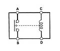
with the relay, you need to connect the green wire and ground the actuator pins of the relay (C & D in my pic) and you will need to connect ground and GRN/WHT to the switch pin (A & B) and do the same with the unlock circuit.
GOOD LUCK
-
thanks D4rk4n63l
i tried this today. but it didn't trigger anything. though in my case, i don't have the grn/wht and grn/orange wires.. so i examined what's left and i had two wires that are thinner coloured blue/red and green/red. so i tested that and nothing happened.
i've actually given up and planning to return the unit and find another unit that will surely work with my car.. hehe but if anyone can suggest anything else, i'd like to try it too.
thanks guys
-
if there is no GRN/WHT and GRN/ORN try probing ground to the rest of the wires and note down which one locks/unlocks the door when you connect ground to it.. just make sure you dont tap the +12V or you'll get a short
 Posting Permissions
- You may not post new threads
- You may not post replies
- You may not post attachments
- You may not edit your posts
-
Forum Rules
|


 Reply With Quote
Bookmarks