

Yes this is exactly right. It means under boost, this valve cannot vent AT ALL. So u plumb it into a negitive pressure which is pre-turbo. This helps! We are lucky with our honda engines, PCV isnt really a big issue. Some engines, ala Nissans will fill your entire intake system with oil in no time. Mainly because they run a little more clearance in the rings..Originally Posted by [ricer]

Once again, this is all normal engine operation.
Ideal setup;
Catch can, everything plumbed from engine to catch can too intake OR exhaust. Use a slash-cut valve in the exhaust to stimulate a low pressure system and pull the air/vapours out of the engine
Acceptable setup, vent everything to atmosphere. Use a filter to be safe. You wont get accelerated contamination of oil by water.. This is false.
Unacceptable setup, One way valve closing this under boost. Not letting the engine vent under boost. This will increase crank case pressure and cause accelerated wear on ur rings, guides and other seals.

 Reply With Quote
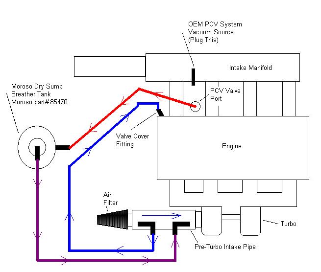


Bookmarks